
OSI and TCP/IP: how a packet actually travels
Why the layered models exist, what each layer adds to a packet, and where OSI and TCP/IP differ.
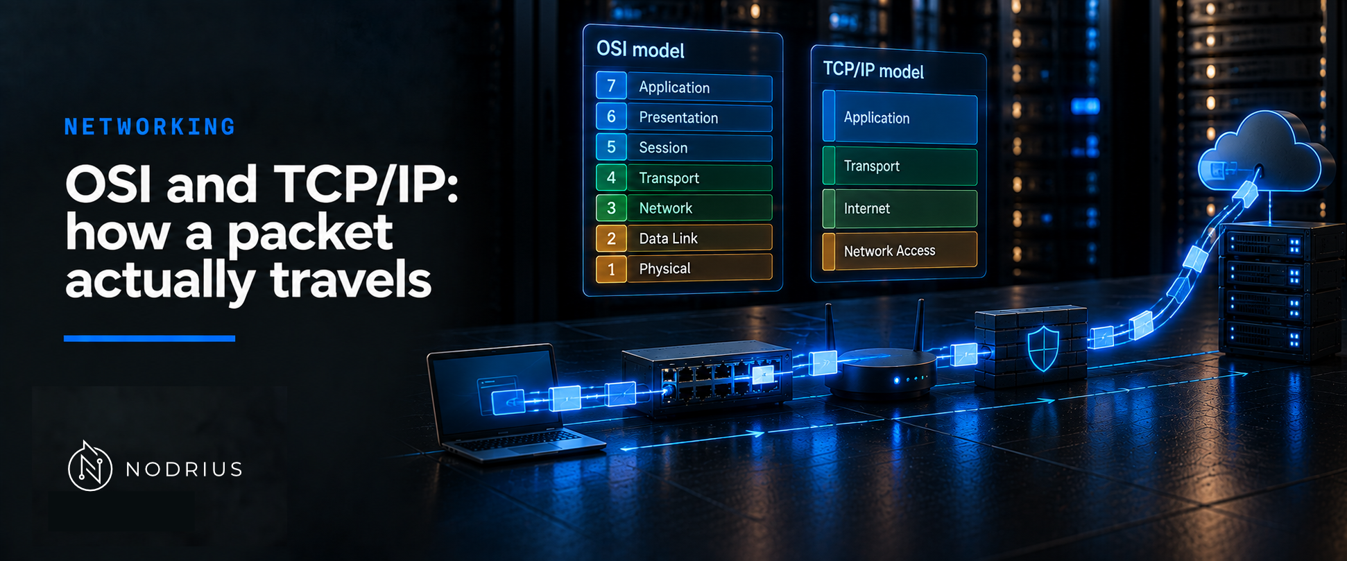
OSI and TCP/IP describe the same journey at two levels of detail. OSI is a seven-layer reference model, written to coordinate standards development and deliberately not an implementation specification. What the internet actually runs is described with four layers in RFC 1122: application, transport, internet, link. The part worth understanding is the wrapping.
The model: wrapping down, unwrapping up
Read the rest through one model: each layer wraps what it receives and hands it to the layer below; the receiver unwraps one header at a time, in reverse. A packet is the sum of the headers added on the way down, nothing more — each header carries what the next step needs, and the protocol that reads it is named by the header above.
SEND
  application data
        ↓
  [TCP header][data]                          segment    (transport)
        ↓
  [IP header][TCP header][data]               packet     (internet)
        ↓
  [link header][IP header][TCP header][data]  frame      (link)
        ↓
  bits on the wire

RECEIVE
  bits on the wire
        ↓
  [link header][IP header][TCP header][data]
        ↓
  [IP header][TCP header][data]
        ↓
  [TCP header][data]
        ↓
  application data
Terms. Frame (link), packet (internet), segment (TCP) and datagram (UDP) name the same idea at different layers; a header is what a layer prepends.
Why the wrapping is layered
ITU-T X.200, identical in text to ISO/IEC 7498-1, defines a layer as a subdivision that interacts directly only with the layer above and the layer below, and a service as what a layer and everything beneath it offer the layer above. An application can then change without touching Ethernet, and a link technology without rewriting the application. Layers divide responsibilities; they do not rank them.
The two models side by side
| OSI (ISO/IEC 7498-1) | TCP/IP (RFC 1122) | Typical content |
|---|---|---|
| Application, Presentation, Session | Application | HTTP, DNS, SSH |
| Transport | Transport | TCP, UDP |
| Network | Internet | IP, ICMP |
| Data Link, Physical | Link | Ethernet, Wi-Fi |
This alignment is a didactic aid, not a normative mapping: RFC 1122 notes that its application layer combines the top two OSI layers, and it keeps no separate physical layer, its link layer covering the protocol used to reach the directly connected network. The five-layer variant common in courses is a teaching device, not a standard.
What each layer adds
On the way down, each layer prepends one header. The link header carries the MAC (Media Access Control) addresses of the current link — turning a destination IP into a MAC address is the ARP and Neighbor Discovery sheet’s subject. The IP header carries the addresses, a hop counter and a protocol number; the transport header carries the ports.
That protocol number makes the unwrapping automatic. RFC 1180 describes each module as a multiplexer downward and a demultiplexer upward: the Ethernet type field decides whether a frame goes to ARP or to IP, and the IP protocol field decides whether the payload goes to TCP or to UDP. The numbers come from IANA: 1 ICMP, 6 TCP, 17 UDP.
The journey, step by step
- The host finds the destination is not local and consults its route table: directly connected networks, plus an indirect route through a next-hop router.
- The frame must reach that next hop first, so the sender needs the MAC address of the router, not of the final destination.
- Each router reads only the destination address, picks the most specific route, decrements the hop counter, writes a new link header for the next link and forwards; addresses and payload are untouched.
- The hop counter stops packets circulating forever: IPv4 calls it Time to Live, an upper bound on a datagram’s lifetime, reduced at every point where it is processed (RFC 791); IPv6 calls it Hop Limit and discards the packet at zero (RFC 8200).
- At the destination the process reverses: the link header is consumed, the IP header names the transport protocol, the transport header names the process, and the application receives the bytes wrapped at the start.
What the model does not promise
IP is best effort: RFC 791 provides no mechanism to augment end-to-end reliability, flow control or sequencing, and RFC 1122 is equally direct — datagrams may arrive damaged, duplicated or out of order, or not at all. Reliability belongs to the transport layer: TCP detects loss and retransmits, UDP guarantees neither delivery nor duplicate protection (RFC 9293; RFC 768). Loss is normal here, not a malfunction.
Size is the other boundary: a path carries no datagram larger than its smallest link — 1500 octets on an Ethernet (RFC 894), 1280 the minimum for every IPv6 link (RFC 8200). Layering is a map of responsibilities, not a guarantee — and not a security boundary.
A common misconception
The OSI model is not what the internet implements: the deployed architecture is the four-layer model of RFC 1122. A layered diagram maps responsibilities — real stacks take shortcuts, and no header is added just because a layer has a name. Layer 4 usually means the transport layer of the deployed stack, not a reference to the standard.
What to remember
- A packet is the sum of the headers added on the way down, nothing more.
- OSI is a seven-layer reference model for standards; TCP/IP is the four-layer architecture in use.
- Routers forward on the destination prefix and the hop counter, never on the payload.
- Best-effort delivery belongs to IP; reliable delivery belongs to the transport protocol.
Level and prerequisites. L1 — fundamentals. No prerequisites; a rough idea of what an IP address is helps, and nothing here requires configuration experience.
Where to go next
- Networking — the area this sheet belongs to.
- The L1 sheets this one hands off to (none published): Ethernet frames and MAC tables, IPv4/IPv6 prefixes and the default gateway, ARP and Neighbor Discovery, ICMP/TCP/UDP and sockets.
References
- ITU-T X.200 (07/94) / ISO/IEC 7498-1:1994 — the OSI reference model.
- RFC 1122 — requirements for Internet hosts; the four-layer architecture (§1.1.3).
- RFC 1180 — an IETF tutorial on encapsulation and demultiplexing.
- RFC 791 — IPv4; Time to Live and best-effort delivery.
- RFC 8200 — IPv6; the Hop Limit rule and the minimum link MTU.
- RFC 894 — IP datagrams over Ethernet; the 1500-octet ceiling.
- RFC 1812 — router forwarding behaviour; the most specific matching route.
- RFC 9293, RFC 768 — TCP and UDP.
- IANA — Protocol Numbers registry.